GB Liquid (น้ำมัน)- coold High-power dccharging Connector ข้อกำหนดทางเทคนิค | |||||||
พารามิเตอร์ทางเทคนิคของขั้วต่อการชาร์จ | |||||||
พารามิเตอร์ทางไฟฟ้า | ความละเอียดของพอร์ต | DC ± | PE PE | ± | CC1 | CC2 | S ± |
ข้อกำหนดการเดินสายไฟ (mm²) | 30-30 | 6. | 1.5 | 0.5 | 0.5 | 0.5 | |
เส้นผ่านศูนย์กลางของขั้วต่อ (มม.) | Φ12 | Φ6 | Φ3 | Φ3 | Φ3 | Φ3 | |
แรงดันไฟฟ้าที่ใช้งาน (DC) | 1000โวลต์ | 0-30โวลต์ | 0-30โวลต์ | 0-30โวลต์ | 0-30โวลต์ | 0-30โวลต์ | |
จัดอันดับปัจจุบัน | 100A (เมื่อระบบทำความเย็นของเหลวไม่ทำงาน) | /// | 10A | 2A | 2A | 2A | |
กระแสไฟทำงานต่อเนื่องสูงสุด | 600A (ความยาวสายและความสามารถในการจัดการความร้อน) | ||||||
เส้นผ่านศูนย์กลางภายนอกของสายเคเบิล | Φ 30มม. ± 0.6 (GROUND Wire 6mm ², แหล่งจ่ายไฟเสริม1.5mm ²) | ||||||
น้ำหนักของตัวเชื่อมต่อ | <1.1กก. (ไม่รวมสาย) | ||||||
ความต้านทานฉนวนกันความร้อน | 2000 mΩ ระหว่าง DC ขั้วบวกและขั้วลบและขั้ว PE (แรงดันทดสอบ1000V DC) | ||||||
ทนต่อแรงดัน (50Hz, AC) | ทดสอบหลังจากเสียบสายไฟ: ① แรงดันความต้านทานระหว่าง DC และ DC-4500 V DC 1นาที; ② DC , DC-และ PE, S , S , A, แรงดันไฟฟ้า A-Resistance 1500 V DC 1นาที ③ PE, แรงดันไฟฟ้าความต้านทาน1500 V DC 1นาทีระหว่าง S , S-, A และ A-; ④ S , S-, CC1, A, แรงดันไฟฟ้า A-Two ของ1500 V D C 1นาที; | ||||||
หมายเหตุ: เส้นผ่านศูนย์กลางภายนอกและพื้นที่หลักของสายเคเบิลสามารถออกแบบและปรับแต่งได้ตามความต้องการที่แท้จริงของลูกค้า | |||||||
คุณสมบัติทางกล | อายุการใช้งาน: | 10000ครั้ง | |||||
ปลั๊กและแรงดึง: | 120N | ||||||
Lock-in Force: | 200N | ||||||
พารามิเตอร์ด้านสิ่งแวดล้อม | ระดับการป้องกันก่อนการแทรก: | IP54 | |||||
เกรดของการป้องกันหลังจากการแทรก: | IP55 | ||||||
IP67 | |||||||
อุณหภูมิแวดล้อม: | -30 ℃ - - 50 ℃ | ||||||
เกรดสารหน่วงไฟของวัสดุฉนวน: | UL94 V-0 | ||||||
วัสดุที่ใช้ในการผลิต | ที่อยู่อาศัย: | พลาสติกวิศวกรรม (PA66ทนอุณหภูมิหรือ PC ทนอุณหภูมิ) | |||||
ขั้ว: | ทองแดง, พื้นผิวชุบเงิน | ||||||
ชิ้นส่วนซีล: | ยางซิลิโคนยาง | ||||||
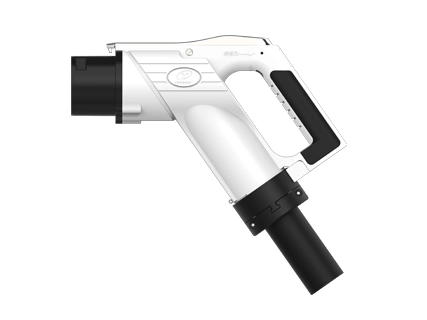
ลักษณะของขั้วต่อการชาร์จ | รูปที่1.1ลักษณะของอินเตอร์เฟซของเหลว (น้ำมัน) ระบายความร้อนด้วย DC ชาร์จเชื่อมต่อ (gb/t 20234-2023) | ||||||
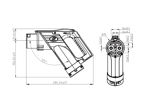
คำจำกัดความของอินเตอร์เฟซ | รูปต่อไปนี้แสดงแผนภาพของอินเทอร์เฟซแถวทองแดงอินเทอร์เฟซสายรัดสัญญาณและอินเทอร์เฟซสายระบายความร้อนระหว่างสายเชื่อมต่อและปลายกอง โครงสร้างต่อไปนี้โดยทั่วไปคือการออกแบบที่กำหนดเอง | ||||||
หน่วยทำความเย็นขนาดกลางของเหลว (ชุดประกอบโมดูลระบายความร้อน HPC) | |||||||
พารามิเตอร์ทางเทคนิค | ตารางที่1: ตารางพารามิเตอร์ทางเทคนิค | ||||||
ขนาดขนาดปกติ | 435 × 155 × 410 (มม.) | พลังงานการกระจายความร้อน | 3.0KW @ 4L/นาที700m 3 /h | ||||
แรงดันไฟฟ้าขาเข้า | DC12V | พาวเวอร์ | ≤ 200วัตต์ | ||||
ระบายความร้อนขนาดกลาง | ไดเมทิลซิลิโคนออยล์ ได-เทอร์ท-บิวทิล-พี-เมทิลฟีนอล น้ำหล่อเย็น TF8016 Fuchs เคส E4 (-40 ~ 85 ℃) | การไหลของความเย็น | 4L/นาที @ 450Kpa | ||||
แรงดันการจ่ายน้ำ | 0.6Mpa | แรงดันใช้งาน | 0 ~ 0.7MPa | ||||
อุณหภูมิในการทำงาน | -40 ℃-50 ℃ | ปริมาณหม้อขยายตัว | 1.5 L | ||||
เสียงตัดเสียงรบกวน | ≤ 60dB(A) | ระดับการป้องกัน | ไอพี68 | ||||
น้ำหนักตัวเครื่อง | 7กิโลกรัมค่ะ | โหมดการสื่อสาร | ขึ้นอยู่กับ Modbus 485/ 232 | ||||
วิธีการควบคุม | ระบบการทำงานอัตโนมัติเต็มรูปแบบ | อายุการใช้งานยาวนานขึ้น | 25000ชม | ||||
คำจำกัดความของหมุดสายไฟ | ตารางที่2คำจำกัดความของหมุดสายไฟ | ||||||
หมายเลขคำสั่งซื้อ | ชื่อของบริษัท | พื้นที่หน้าตัดของ ลวด (mm²) | รุ่นขั้วต่อ | หมายเหตุหมายเหตุ | |||
1. | สัญญาณกราวด์ | 0.5 | E0508 | Ci คริส | |||
2. | A (485 การสื่อสาร)/ 485-A | 0.5 | E0508 | Ci คริส | |||
3. | A- (485) การสื่อสาร) 485-B | 0.5 | E0508 | Ci คริส | |||
4. | เปิดใช้งานพัดลม | 0.5 | E0508 | การควบคุมพลังงานพัดลม | |||
5. | การเปิดใช้งานพัดลม- | 0.5 | E0508 | การควบคุมพลังงานพัดลม | |||
6. | 12โวลต์/24โวลต์ | 1.0 | TVS1.25-4 | ตัวควบคุมแหล่งจ่ายไฟ | |||
7นิ้ว7นิ้ว | GND สำหรับ | 2.5 | TVS2-4 | ตัวควบคุมแหล่งจ่ายไฟ | |||
8นิ้ว8นิ้ว | ปั๊มเปิดใช้งาน | 0.5 | E0508 | ปั๊มควบคุมพลังงาน | |||
9. | ปั๊มเปิดใช้งาน- | 0.5 | E0508 | ปั๊มควบคุมพลังงาน | |||
10 10ชิ้น | ปั๊ม12V / 24V | 1.0 | TVS2-4 | ปั๊มควบคุมพลังงาน | |||
11 11ค่ะ | พัดลม: 12V / 24V | 1.0 | TVS2-4 | แหล่งจ่ายไฟพัดลม | |||
ข้อควรระวังด้านความปลอดภัย | ผลิตภัณฑ์นี้ใช้ของเหลวฉนวนเป็นสื่อระบายความร้อนหากการเปลี่ยนโดยไม่ได้รับอนุญาตอาจนำไปสู่การลดลงหรือความเสียหายของโครงสร้างการปิดผนึกของโมดูลระบายความร้อนหรือแม้กระทั่งทำให้เกิดความเสียหายของสายเชื่อมต่อ ฝาของหม้อขยายเต็มไปด้วยสื่อระบายความร้อนและเปิดเมื่อจำเป็น ในกรณีอื่นๆฝาปิดอยู่ในสภาพแน่นเพื่อป้องกันไม่ให้ฝุ่นอนุภาคขนาดเล็กน้ำและสารอื่นๆเข้ามาเพื่อหลีกเลี่ยงการอุดตันหรืออุบัติเหตุด้านความปลอดภัย ห้ามสัมผัสมือในการทำงานของผลิตภัณฑ์เพื่อป้องกันไม่ให้พัดลมทำร้ายมือ อย่าสัมผัสหม้อน้ำในระหว่างการทำงานของผลิตภัณฑ์เพื่อป้องกันการลวก | ||||||
การทำความสะอาดและบำรุงรักษา | ทำความสะอาดเฉพาะเมื่อผลิตภัณฑ์ไม่ได้รับพลังงาน ทำความสะอาดชิ้นส่วนไฟฟ้าและชิ้นส่วนที่เหลือด้วยผ้าแห้ง ห้ามใช้ผงซักฟอกขั้วต่อน้ำขั้วต่อไอน้ำที่มีฤทธิ์กัดกร่อนในการทำความสะอาด ชิ้นส่วนผลิตภัณฑ์ส่วนใหญ่เป็นพลาสติกเทอร์โมพลาสติกไม่ทำให้ผลิตภัณฑ์ได้รับผลกระทบจากแรงภายนอกเพื่อไม่ให้ส่งผลกระทบต่อการใช้งานความลับ ในระหว่างการใช้ผลิตภัณฑ์ควรตรวจสอบระดับของเหลวของหม้อขยายอย่างสม่ำเสมอเพื่อหลีกเลี่ยงความล้มเหลวของเซ็นเซอร์ระดับของเหลว ความเสียหายของผลิตภัณฑ์และอุบัติเหตุด้านความปลอดภัยที่เกิดจากการเตือนภัย ระยะเวลาการตรวจสอบที่แนะนำคือไตรมาสละครั้ง ตรวจสอบผลิตภัณฑ์อย่างสม่ำเสมอเพื่อการรั่วซึม |
GB Liquid (น้ำ)- coold High-power DC CHARGING Connector ข้อกำหนดทางเทคนิค | |||||||
พารามิเตอร์ทางเทคนิคของขั้วต่อการชาร์จ | |||||||
พารามิเตอร์ทางไฟฟ้า | ความละเอียดของพอร์ต | DC ± | PE PE | ± | CC1 | CC2 | S ± |
ข้อกำหนดการเดินสายไฟ (mm²) | 48นิ้ว48นิ้ว | 6. | 1.5 | 0.5 | 0.5 | 0.5 | |
เส้นผ่านศูนย์กลางของขั้วต่อ (มม.) | Φ12 | Φ6 | Φ3 | Φ3 | Φ3 | Φ3 | |
แรงดันไฟฟ้าที่ใช้งาน (DC) | 1000โวลต์ | 0-30โวลต์ | 0-30โวลต์ | 0-30โวลต์ | 0-30โวลต์ | 0-30โวลต์ | |
จัดอันดับปัจจุบัน | 125A (เมื่อระบบทำความเย็นของเหลวไม่ทำงาน) | /// | 10A | 2A | 2A | 2A | |
กระแสไฟทำงานต่อเนื่องสูงสุด | 500A (ความยาวสายและความสามารถในการจัดการความร้อน) | ||||||
เส้นผ่านศูนย์กลางภายนอกของสายเคเบิล | Φ28mm ± 0.6 | ||||||
น้ำหนักของตัวเชื่อมต่อ | <1.1กก. (ไม่รวมสาย) | ||||||
ความต้านทานฉนวนกันความร้อน | 2000 mΩ ระหว่าง DC ขั้วบวกและขั้วลบและขั้ว PE (แรงดันทดสอบ1000V AC) | ||||||
ทนต่อแรงดัน (50Hz, AC) | ทดสอบหลังจากเสียบสายไฟ: ① แรงดันความต้านทานระหว่าง DC และ DC-4500 V DC 1นาที; ② DC , DC-และ PE, S , S , A, แรงดันไฟฟ้า A-Resistance 1500V AC 1นาที; ③ PE, แรงดันไฟฟ้าความต้านทาน1500V AC 1นาทีระหว่าง S , S-, A และ A-; ④ S , S-, CC1, A, แรงดันไฟฟ้า A-Two ของ1500V AC 1นาที; | ||||||
หมายเหตุ: เส้นผ่านศูนย์กลางภายนอกและพื้นที่หลักของสายเคเบิลสามารถออกแบบและปรับแต่งได้ตามความต้องการที่แท้จริงของลูกค้า | |||||||
ประสิทธิภาพทางกล | อายุการใช้งาน: | 10000ครั้ง | |||||
ปลั๊กและแรงดึง: | 120N | ||||||
Lock-in Force: | 200N | ||||||
พารามิเตอร์ด้านสิ่งแวดล้อม | ระดับการป้องกันก่อนการแทรก: | IP54 | |||||
เกรดของการป้องกันหลังจากการแทรก: | IP55 | ||||||
อุปกรณ์ไฟฟ้าแรงสูง: | IP67 | ||||||
อุณหภูมิแวดล้อม: | -30 ℃ - - 50 ℃ | ||||||
เกรดสารหน่วงไฟของวัสดุฉนวน: | UL94 V-0 | ||||||
วัสดุทำจากวัสดุ | ที่อยู่อาศัย: | พลาสติกวิศวกรรม (PA66ทนอุณหภูมิหรือ PC ทนอุณหภูมิ) | |||||
ขั้ว: | ทองแดง, พื้นผิวชุบเงิน | ||||||
ชิ้นส่วนซีล: | ยางซิลิโคนยาง | ||||||
คำจำกัดความของอินเตอร์เฟซ | รูปต่อไปนี้แสดงแผนภาพของอินเทอร์เฟซแถวทองแดงอินเทอร์เฟซสายรัดสัญญาณและอินเทอร์เฟซท่อระบายความร้อนระหว่างสายเชื่อมต่อและปลายกอง โครงสร้างต่อไปนี้โดยทั่วไปคือการออกแบบที่กำหนดเอง | ||||||
รูปที่2แผนภาพของอินเทอร์เฟซเสาเข็มเข้าของสายเชื่อมต่อ (สำหรับการอ้างอิง) | |||||||
หน่วยทำความเย็นขนาดกลางของเหลว (ชุดประกอบโมดูลระบายความร้อน HPC) | |||||||
พารามิเตอร์ทางเทคนิค | ตารางที่1.ตารางพารามิเตอร์ทางเทคนิค | ||||||
ขนาดขนาดปกติ | 306 × 136 × 358 (มม.) | การเปลี่ยนความร้อน | 1.6KW(50 ℃) | ||||
แรงดันไฟฟ้าขาเข้า | DC12V/24V ค่ะ | พาวเวอร์ | ≤ 160วัตต์ | ||||
ปัจจุบันปัจจุบัน | พัดลม (12V) | 9A สูงสุด | |||||
ปั๊ม (12V) | 7A สูงสุด | ||||||
ระบายความร้อนขนาดกลาง | สารละลายป้องกันการแข็งตัว (น้ำ เอทิลีนไกลคอล) | การไหลของความเย็น | 0-2.5L/นาทีปรับได้ | ||||
การจ่ายน้ำ ความดันความดันสูง | 6bar | แรงดันใช้งาน | 0-6bar | ||||
อุณหภูมิในการทำงาน | -30 ℃-50 ℃ | ปริมาณหม้อขยายตัว | 1.5 L | ||||
เสียงตัดเสียงรบกวน | ≤ 60dB(A) | ระดับการป้องกัน | ไอพี68 | ||||
น้ำหนักตัวเครื่อง | 3.5กิโลกรัมค่ะ | โหมดการสื่อสาร | ขึ้นอยู่กับ Modbus 485/ 232 | ||||
คำจำกัดความของหมุดสายไฟ | ตารางที่2.ตารางคำจำกัดความของหมุดสายไฟ | ||||||
ไม่นะครับ | ชื่อของบริษัท | พื้นที่หน้าตัดของ ลวด (mm²) | รุ่นขั้วต่อ | หมายเหตุหมายเหตุ | |||
1. | สัญญาณกราวด์ | 0.5 | E0508 | Ci คริส | |||
2. | A (485 การสื่อสาร)/ 485-A | 0.5 | E0508 | Ci คริส | |||
3. | A- (485) การสื่อสาร) 485-B | 0.5 | E0508 | Ci คริส | |||
4. | เปิดใช้งานพัดลม | 0.5 | E0508 | การควบคุมพลังงานพัดลม | |||
5. | การเปิดใช้งานพัดลม- | 0.5 | E0508 | การควบคุมพลังงานพัดลม | |||
6. | 12โวลต์/24โวลต์ | 1.0 | TVS1.25-4 | ตัวควบคุมแหล่งจ่ายไฟ | |||
7นิ้ว7นิ้ว | GND สำหรับ | 2.5 | TVS2-4 | ตัวควบคุมแหล่งจ่ายไฟ | |||
8นิ้ว8นิ้ว | ปั๊มเปิดใช้งาน | 0.5 | E0508 | ปั๊มควบคุมพลังงาน | |||
9. | ปั๊มเปิดใช้งาน- | 0.5 | E0508 | ปั๊มควบคุมพลังงาน | |||
10 10ชิ้น | ปั๊ม12V / 24V | 1.0 | TVS2-4 | ปั๊มควบคุมพลังงาน | |||
11 11ค่ะ | พัดลม: 12V / 24V | 1.0 | TVS2-4 | แหล่งจ่ายไฟพัดลม |
Liquid medium cooling unit (HPC cooling module assembly)
The HPC cooling module assembly (HPC-CU) is used for intelligent high-power charging (HPC) technology. The heat dissipation power of 3.0KW can bring the charging current up to 600A, while ensuring the safe and stable operation of the combined charging connection system (CCS). The core technology of this product is to provide coolant with appropriate temperature and flow to CCS under full working conditions, so as to ensure that the temperature of CCS relative to the ambient temperature is not more than 50K (ΔTmax = 50K) during charging.
2. Principle
HPC CCS Charging can transport more than 600A charging current, the use of conventional charging technology requires the use of heavy cables or often lead to CCS overheating, in order to facilitate charging operation, intelligent HPC charging technology adopts liquid cooling system, the system HPC cooling module assembly uses environmental protection cooling medium to provide cooled source to CCS, easy to maintain. The cooling medium can simultaneously cool the cable and the DC power terminal of the charging connector.
Charging connector terminal has excellent thermal conductivity, so it can also act as a radiator in the charging process.
A closed loop connecting the HPC cooling module assembly inlet and outlet tube to the CCS outlet tube and inlet tube, The cooling medium is driven by the circulating pump, CCS Transfer of the generated heat to the circulating cooling medium, The cooling medium then transfers the heat to the radiator, The radiator then achieves continuous heat dissipation through an electronic fan blower, In this process, The module collects real-time inlet and outlet liquid temperature through the sensor, Adjust the rotational speed of the pump and fan according to the collected temperature, Realize the real-time adjustment of the heat dissipation power, Put the CCS within a suitable working range, So as to ensure the safety and stability of HPC charging pile.
Figure 1. Schematic diagram of the high-power charging and cooling system
3. Product diagram of high-power charging liquid cooling system (W)
Figure 2. Product diagram of the liquid-cooling system
Automatic control program (standby mode, automatic mode, sleep mode, fault mode, etc.), can prolong the life and save energy.
5. Installation dimensions
Figure 3. Installation dimensions of bottom plate (optional)
Figure 4. Installation dimensions of the bottom plate (customizable)
6. Block diagram of electrical control principle
Figure 5. Schematic block diagram of electrical control
The functions of the controller include: collecting the sensor information, collecting the abnormal fault information, communicating with the charging pile end, and adjusting the pump and fan speed.
1) Collect the sensor information
The temperature and pressure of the inlet fluid and the temperature of the return fluid.
2) Collect the abnormal fault information
Collect fan fault, pump fault, temperature sensor fault, temperature and pressure sensor fault, high temperature, high pressure, low pressure, high level and low level.
3) Charging pile terminal communication
The controller sends the collected normal information and the abnormal information.
For example, receive information about "whether to be charging", "whether to limit current charging", "whether debugging and maintenance", and the temperature value of charging pile collection, etc.
4) Control the fan and the pump
The controller compares the collected current temperature with the set upper temperature limit (such as 90℃) (e.g., the current inlet liquid temperature and the current inlet liquid temperature upper limit), uses the control algorithm to obtain the target speed of the fan and pump, and then adjusts the pump speed and fan speed.
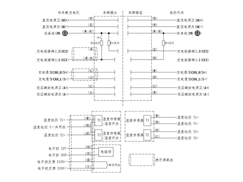
Figure 6. Definition diagram of the wiring pin
7. Matters needing attention
A. Product supplementary description
The above test data do not represent the temperature rise data of all models of liquid-cooled charging connectors, but should be comprehensively considered according to the wire diameter, cable length, the power of the radiator matched by the system and the pump (the flow of coolant circulation) (our company will provide full technical support);
The product conforms to GB / T 20234.1-2023;
Liquid-cooled cable is customized cable, no standard cable, its performance (such as mechanical strength, etc.) can refer to the relevant provisions of GB / T 33594-2017, IEC 62893-4-1 / 2, but temporarily cannot pass the certification;
B. Notes for use
Charging connector coolant is recommended to choose insulating liquid such as Shell E4 and TF8016 Foss coolant;
Unfixed accessories model of the heating management system (such as oil pump, radiator, etc.), conduct comprehensive analysis and experiment for power matching of the accessories according to the customer's current carrying requirements, charging curve, charging connector line length and other requirements;
It is recommended to use the connector line manufacturer to specify the thermal management system (pump, radiator, temperature sensor, control program, etc., integration), and also to provide the cooling system matching and selection support;
The rated working pressure of the connector line is 5Bar, meeting the minimum flow rate of thermal management is 4L / min;
Other cooling medium other than the coolant specified by the manufacturer is prohibited, and the mixing of the cooling medium is prohibited.
National standard liquid (water) cooled DC charging connector
1. Product model and interface standard:
The internal model of the product is YGC1352A-EV-P9P-500XL1, and the interface standard of liquid (water) cooled DC charging connector meets the requirements of GB / T 20234.3-2023 standard.
2. Introduction of product advantages
And the product relative to the conventional national standard dc charging connector rated voltage (1000V), the current larger (depending on specific charging strategy, through the 500A, 30 minutes current test), charging power, charging efficiency is higher, can truly solve the new energy vehicles users charging anxiety, the test data 3-5 minutes can supplement the new energy vehicles driving 100 Km electricity.
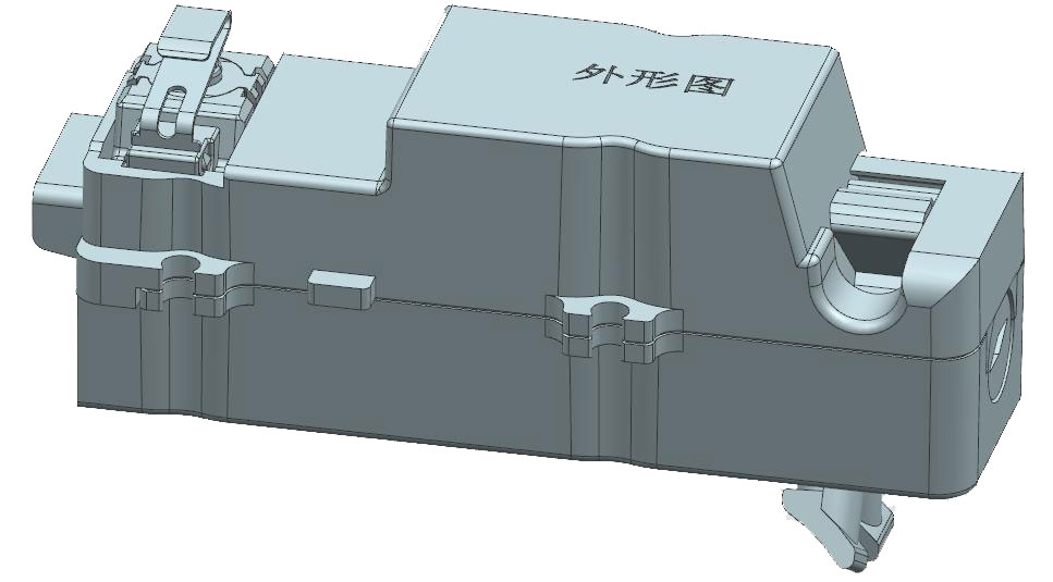
3. Appearance of the charging connector
Figure 1. Appearance of Yonggui National Standard (GB / T 20234-2015) interface liquid (water) cooled DC charging connector
Liquid medium cooling unit (HPC cooling module assembly)
1. Product Introduction
HPC cooling module assembly (HPC-CU) is used for intelligent high-power charging (HPC) technology. The heat dissipation power is 1.6KW, which enables the charging current to reach 500A, and ensures the safe and stable operation of GB DC charging connector line assembly (referred to as DC charging connector line). The core technology of this product is to provide coolant with appropriate temperature and flow to the DC charging connector under full working conditions, so as to ensure that the temperature of the DC charging connector does not rise more than 50K (ΔTmax = 50K).
2. Principle
HPC DC charging connector line can transfer more than 500A when charging current. Using conventional charging technology needs to use heavy cable or often lead to overheating of DC charging connector line. In order to facilitate charging, intelligent HPC charging technology adopts liquid cooling system. HPC cooling module assembly in this system uses environmentally friendly cooling medium to provide cooled source for DC charging connector line and is easy to maintain.
The cooling medium can simultaneously cool the cable and the DC power terminal of the charging connector. Charging connector terminal has excellent thermal conductivity, so it can also act as a radiator in the charging process. The closed loop is formed by connecting the incoming and outlet pipes with the HPC cooling module assembly and the inlet pipe of the DC charging connector line, The cooling medium is driven by the circulating pump, The DC charging connector line transfers the generated heat to the circulating cooling medium, The cooling medium then transfers the heat to the radiator, The radiator then achieves continuous heat dissipation through an electronic fan blower, In this process, The module collects real-time inlet and outlet liquid temperature through the sensor, Adjust the rotational speed of the pump and fan according to the collected temperature, Realize the real-time adjustment of the heat dissipation power, So that the DC charging connector line is in a suitable working range, So as to ensure the safety and stability of HPC charging pile.
Figure 2. Schematic diagram of the high-power charging and cooling system
Figure 3. Product diagram of the water-cooling system
4. Functional features
⑴ Car standard grade products
Design and development, component selection, experimental verification, manufacturing process and quality control are all developed in accordance with the vehicle specification level IATF16949 system.
⑵ IP68 protection
Fully prevent dust from entering the internal core components, in not more than 1 m deep water immersion, clean can work normally.
⑶ Miniaturization
Lightweight, integrated, and small in size.
⑷ Energy saving
According to the charging condition, the output power of the fan and water pump is automatically adjusted to achieve energy saving.
⑸ Automatization
Automatic control program (standby mode, automatic mode, sleep mode, fault mode, etc.), can prolong the life and save energy.
5. Installation dimensions
Figure 4. Installation dimensions diagram
6. Block diagram of electrical control principle
Figure 5. Block diagram of electrical control principle
The functions of the controller include: collecting the sensor information, collecting the abnormal fault information, communicating with the charging pile end, and adjusting the pump and fan speed.
⑴ Collect the sensor information
The temperature and pressure of the inlet fluid and the temperature of the return fluid.
⑵ Collect abnormal fault information
Collect fan fault, pump fault, temperature sensor fault, temperature and pressure sensor fault, high temperature, high pressure, low pressure, high level and low level.
⑶ Charging pile terminal communication
The controller sends the collected normal information and the abnormal information.
For example, receive information about "whether to be charging", "whether to limit current charging", "whether debugging and maintenance", and the temperature value of charging pile collection, etc.
⑷Control the fan, and the pump
The controller compares the collected current temperature with the set upper temperature limit (such as 90℃) (e. g., the current inlet liquid temperature and the current inlet liquid temperature upper limit), uses the control algorithm to obtain the target speed of the fan and pump, and then adjusts the pump speed and fan speed.
7. Definition of the wiring pin
Figure 6. Definition diagram of the wiring pin
8. Matters needing attention
8.1. Product supplementary description
⑴ High-power liquid-cooled charging connector has no corresponding national and industry standards, so it cannot pass the strong inspection certification;
⑵ Liquid-cooled cable is customized cable, no standard cable, its performance (such as mechanical strength, etc.) can refer to the relevant provisions of GB / T 33594-2017, IEC 62893-4-1 / 2, but can not pass the certification;
⑶ Because there is a cooling pipeline inside the liquid-cooled connector line, the connection fixed structure with the pile end cannot directly follow the cable tightening structure of the conventional DC charging connector line. According to the different shape of the charging pile and the internal electrical design, the connection structure of the connector line and the pile needs to customize the design.
8.2. Notes for use
⑴ Charging connector coolant must be selected vehicle coolant (can be 50% ethylene glycol aqueous solution, but need to use deionized water), it is recommended to purchase through regular channels, prohibit self-blending;
⑵ It is strongly recommended to use the liquid medium cooling device (HPC cooling module assembly) designated by the connector line manufacturer. After selecting the cooling device, the pressure and flow rate should be matched and adjusted. The rated working pressure of the connector line is <1Bar, which can meet the minimum flow rate of 1L / min of thermal management;
⑶ No cooling medium other than the coolant specified by the manufacturer, the mixing of cooling medium, and the cooling system filled with cooling medium such as dimethyl silicone oil.
⑷ Expansion pot lid in the filling cooling medium and open when necessary, the rest of the situation to ensure that in the tight state, to prevent dust, small particles, water and other substances from entering, so as to avoid blockage or safety accidents.
⑸ It is forbidden to touch the product work, to prevent the fan injured hand.
⑹ Do not touch the radiator during the product work to prevent scald.
⑺ Can only when the product is not powered up, use dry cloth to clean electrical parts and other parts, do not use corrosive detergent, water connector, steam connector for cleaning.
⑻ Most of the product parts are thermoplastic, do not make the product is impacted by external forces, so as not to affect the use.
ขั้วต่อการตัดเย็บตามความต้องการเฉพาะของคุณ
ให้การแก้ปัญหาระบบ
ตอบสนองต่อความต้องการภายใน12ชั่วโมง